Karnataka 1st PUC Electronics Question Bank Chapter 4 Passive Electronic Components
One Mark Questions and Answers
Question 1.
What is an active component?
Answer:
An active component is a component that supplies energy to a circuit.
Question 2.
What is a passive component?
Answer:
A passive component is a component that dissipates energy and does not supply energy to a circuit.
![]()
Question 3.
Give any one example for the active component.
Answer:
Transistor.
Question 4.
Give any one example for the passive component.
Answer:
Capacitor.
Question 5.
What does the power rating of a resistor indicate?
Answer:
Power rating indicates the maximum power a resistor can withstand safely.
![]()
Question 6.
What is meant by tolerance of a resistor?
Answer:
Tolerance is the percentage variation in the resistance value from the value specified by the colour code.
Question 7.
Define the temperature coefficient of resistance of a material.
Answer:
Temperature coefficient of resistance is defined as the ratio of increase in resistance per °C rise in temperature to its resistance at 0°C
Question 8.
Define resistivity or specific resistance of a material.
Answer:
The resistivity of the material is defined as the resistance of a conductor of unit length having a unit area of cross-section.
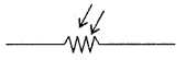
Question 9.
Draw the circuit symbol of the potentiometer.
Answer:

Question 10.
What does the fourth band of a 4 band colour coded resistor indicate?
Answer:
Tolerance.
![]()
Question 11.
What does the fifth band of a 5 band colour coded resistor indicate?
Answer:
Tolerance.
Question 12.
What is an SMD resistor?
Answer:
SMD resistor is an electronic component without connecting wires that are soldered directly onto the surface of printed circuit boards.
Question 13.
What is the resistance value of the SMD resistor with code 223?
Answer:
223 = 22 × 103Ω = 22KΩ.
Question 14.
Draw the circuit symbol of presets.
Answer:
![]()
Question 15.
Draw the symbol of the electrolytic capacitor.
Answer:
![]()
Question 16.
Write an expression for energy stored ¡n a capacitor.
Answer:
E = \(\frac{1}{2}\)CV2
Question 17.
How do you connect a number of capacitors to obtain the maximum capacitance value?
Answer:
In parallel.
![]()
Question 18.
Name the only type of capacitor which is polarity sensitive.
Answer:
Electrolytic capacitor.
Question 19.
Write an expression for the capacitance of a parallel plate capacitor.
Answer:
C = \(\frac{\varepsilon_{0} \varepsilon_{1} \mathrm{~A}}{\mathrm{~d}}\)
Question 20.
Which has more inductance, a coil with an air core or with an iron core?
Answer:
Iron core inductor has more inductance.
Question 21.
Write an expression for effective inductance when inductors are connected in series.
Answer:
Ls = L1 + L2.
Question 22.
Define transformers efficiency.
Answer:
The efficiency of a transformer is the ratio of output power to input power.
![]()
Question 23.
What is the principle of transformer?
Answer:
Mutual induction.
Question 24.
Write the relation between turns ratio, voltage ratio and current ratio in a transformer.
Answer:
\(\frac{\mathrm{N}_{\mathrm{S}}}{\mathrm{N}_{\mathrm{P}}}=\frac{\mathrm{V}_{\mathrm{S}}}{\mathrm{V}_{\mathrm{p}}}=\frac{\mathrm{I}_{\mathrm{p}}}{\mathrm{I}_{\mathrm{S}}}\)
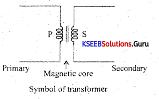
Question 25.
Draw the symbol of a transformer.
Answer:
Question 26.
Can a step-up transformer be used as a step-down transformer?
Answer:
Yes, only when the current is small.
Question 27.
What would be the voltage across the secondary of a transformer with DC voltage across the primary?
Answer:
Zero.
Question 28.
Expand NTC, PTC.
Answer:
NTC = Negative temperature coefficient
PTC = Positive temperature coefficient.
![]()
Question 29.
What is meant by temperature sensors?
Answer:
The temperature sensor is a device that collects data about temperature from a source and converts it to a form that can be understood by another device.
Question 30.
What for LM 35 is used? ,
Answer:
LM 35 series are precision 1C temperature sensor.
Question 31.
Draw the symbol of LDR?
Answer:
Two Mark Questions and Answers
Question 1.
Write four important characteristics of resistors.
Answer:
- ohm rating
- power rating
- Tolerance.
- Temperature coefficient.
Question 2.
Mention the factors on which the capacitance of a capacitor depends.
Answer:
The capacitance of a capacitor depends on
- the area of plates of the capacitor.
- distance between two plates
- dielectric constant of the material between the two plates.
Question 3.
Mention four types of capacitors.
Answer:
- Ceramic capacitors
- Polystyrene capacitors
- Electrolytic capacitors
- Surface-mounted capacitor (SMD capacitor).
Question 4.
Mention four types of materials used as a dielectric between the plates of the capacitor.
Answer:
- Ceramic
- Polystyrene
- Mica
- Paper.
Question 5.
List the factors on which the self-inductance of a coil depends.
Answer:
Self-inductance of a coil depends on
- number of turns in the coil
- length of the coil
- relative permeability of the coil
- The cross-sectional area of the coil.
![]()
Question 6.
Mention the types of inductors.
Answer:
- Air core inductor.
- Iron core inductor.
- Ferrite core inductor.
Question 7.
Name the factors on which the mutual inductance of a pair of coils depends.
Answer:
Mutual inductance depends upon.
- length of the coil
- number of turns in two coils
- relative permeability of the coil.
![]()
Question 8.
Mention different types of transformers.
Answer:
- Power transformer
- Audio frequency transformer
- Radiofrequency transformer
- Intermediate frequency transformer
- Pulse transformer.
Question 9.
Distinguish between tweeter and woofer.
Answer:
A single speaker can not reproduce a wide range of audio frequencies (20 Hz to 20 kHz). Woofers are speakers used to produce low frequencies. Tweeters are speakers used to reproduce high frequencies.
Question 10.
Distinguish between speaker and microphone.
Answer:
The speaker converts an electrical signal into a corresponding audio signal. Microphone converts sound energy into a corresponding electrical signal.
Question 11.
Write applications of thermistors.
Answer:
Thermistors are used in
- temperature measurement
- temperature control in air conditioners.
- alarm systems
- liquid level detection.
Question 12.
Write applications of LDR.
Answer:
LDRs are used
- to switch on street lights automatically
- in automatic headlights
- in counters
- in security systems
- in light and dark activated switches and alarms.
![]()
Question 13.
What is a capacitor? Mention S.l. unit of capacitance.
Answer:
The capacitor is a device that is used to store charges. S.l. unit of capacitance is farad (F).
Question 14.
What is an inductor? Define the unit of inductance.
Answer:
An inductor is a passive component in which an emf is produced whenever there is a change in the currents flowing through it.
Question 15.
S.I unit of inductance is henry (H).
Answer:
The inductance of a coil is one henry if an emf of IV is induced in it when the current through the coil changes at the rate of one ampere per second.
Question 15.
Write the applications of chokes and relays.
Answer:
Chokes are used in
- tube light sets
- in radio and TV receivers
- in power supplies
- in RF tuning circuits.
Relays are used
- as a protective device
- to realise logic functions
- as counters
- as an automatic switching device to operate street lights, UPS, buzzers.
Question 16.
Find resistance values of resistors with the following colour codes.
(i) Brown black silver gold
Answer:
(10 × A+ B) × Multiplier ± Tolerance = (10 × 1 + 10) × 0.01 ± 5% = 0.1Ω ± 5%
(ii) Yellow violet Green silver
Answer:
(10 × 4 + 7) × 105 ± 10% = 47 × 10Ω ± 10%
= 4.7 × 10⁶Ω ± 10%
= 4.7 MΩ ± 10%
(iii) Orange orange red
Answer:
(10 × 3 +3) × 102 ± 20% = 3300 ± 20%
= 3.3 KΩ ± 20%
![]()
Question 17.
Find the resistance values of resistors with following colour bands.
(i) Brown black orange brown
Answer:
(100 × A+ 10 × B + C) × Multiplier± Tolerance
= (100 × 1 + 10 × 0 + 0) × 1 KΩ ± 1% = 100KΩ ± 1%
(ii) Yellow violet black green red
Answer:
(100 × 4 + 10 × 7 + 0) × 100KΩ ± 2%
= 470 × 100KΩ ± 2% = 47.0 × 10⁶Ω ± 2%
= 47MΩ ± 2%.
(iii) Blue-grey red blue-green.
Answer:
(100 × 6 + 10 × 8 + 2) × 100KΩ ± 5% .
= 682 × 100KΩ ± 5% = 68.2 × 1060 ± 5%
= 68.2 MΩ ± 5%
Question 18.
Find the resistance values of the following SMD resistors.
(i) 430
Answer:
R = 430 = 43 × 10° = 43 × 1 =43Ω
(ii) 492
Answer:
R = 492 = 49 × 102 = 4900Ω = 4.9K
(iii) 106
Answer:
R = 106 = 10 × 106 = 10MΩ
(iv) 5R8
Answer:
R = 5R8 = 5.8Ω
![]()
(v) 0R34
Answer:
R = 0R34 = 0.34Ω
(vi) 562
Answer:
R = 562 = 56 × 102 = 5600Ω = 5.6KΩ
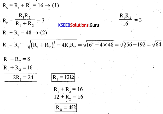
Question 19.
The effective resistance of two resistors connected in series is 16Ω and when connected in parallel is 30Ω. Find the resistance of individual resistors.
Answer:
Question 20.
Write the colour codes for 5 band colour resistors with the following resistance values.
Answer:
1. 10KΩ ± 2%
Answer:
10KΩ ± 2% = 10 × 103 ± 2% = 100 × 102 ±2%
= (100 × 1 + 10 × 0 + 0) × 102 ± 2%
= Brown black black red red.
2. 4.7KΩ ± 1%
Answer:
4.7 KΩ ± 1% = 4.7 × 10³ ± 1% = 47 × 102 ± 1%
= yellow violet black brown
![]()
3. 152 Ω ± 1%
Answer:
152 KΩ ± 1% = (100 × 1 + 10 × 5 + 10° × 2) × 103Ω ± 1% = Brown, green, red; orange, brown.
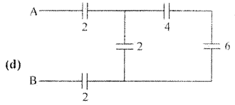
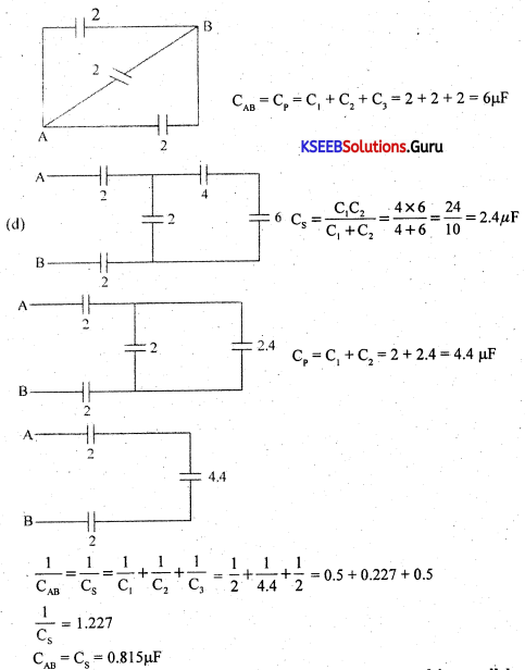
Question 21.
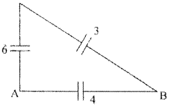
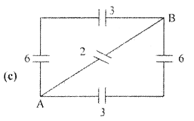
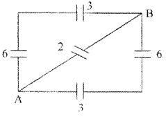
Calculate effective capacitance between A and B in the following figures
(AH values in μF).
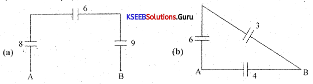
Answer:
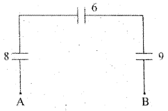
\(\frac{1}{\mathrm{C}_{\mathrm{s}}}=\frac{1}{\mathrm{C}_{1}}+\frac{1}{\mathrm{C}_{2}}+\frac{1}{\mathrm{C}_{3}}=\frac{1}{8}+\frac{1}{6}+\frac{1}{9}=\frac{9+12+8}{72}=\frac{29}{72}\)
CAB = CS = \(\frac{72}{29}\) = 2.49 μF
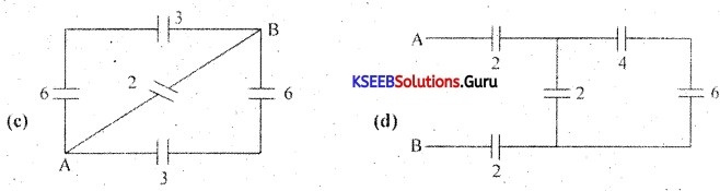
CS = \(\frac{C_{1} C_{2}}{C_{1}+C_{2}}+\frac{6 \times 3}{6+3}=\frac{18}{9}\) = 2 μF
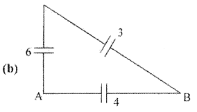
Answer:
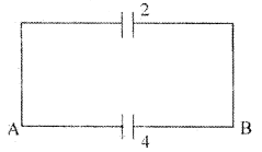
CAB = Cp + C1 + C2 = 2 + 4 = 6 μF
Answer:
![]()
CS = \(\frac{\mathrm{C}_{1} \mathrm{C}_{2}}{\mathrm{C}_{1}+\mathrm{C}_{2}}=\frac{6 \times 3}{6+3}=\frac{18}{9}\) = 2 μF
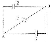
CAB = Cp + C1 + C2 + C3 = 2 + 2 + 2 = 6 μF
Answer:
![]()
Question 22.
Two capacitors of capacitances 3pF and 12pF are connected in parallel across a 30V power supply. Determine
(i) Effective capacitance of the combination
Answer:
C = C1 + C2 = 3 + 12 = 15 μF
(ii) charge on each capacitor and
Answer:
Q1 = C1V1 = 3 × 10-12 × 30 = 90 × 10-12 = 90pC
Q2 = C2V2 = 12 × 10-12 × 30 = 360P
![]()
(iii) total charge on the combination.
Answer:
QT = Q1 + Q2 = 90 + 360 = 450PC.
Three Mark Questions and Answers
Question 1.
Explain the construction of wire wound resistors. Write any one of its applications.
Answer:
Wire wound resistor is made by winding a wire of known length on a hollow porcelain tube.
Eureka wire, an alloy of 60% nickel and 40% copper, is used as a resistance wire. Tinned copper leads are attached to the ends of the winding for connection. The entire assembly is covered with a protective insulation coating of porcelain. The length, thickness and specific resistivity of the resistance wire determine the resistance value. Their resistance varies from 1Ω to 1000Ω. They are available with a power rating from 5 W to 100W. Wire wound resistors have good stability, reliability and high power ratings. The resistance value and the power ratings are printed on the body of the resistance. These resistors are used in audio frequency applications.
Question 2.
Explain the construction of a carbon composition resistor.
Answer:
A mixture of finely divided carbon and a powdered insulating material forms the resistor element. The mixture is moulded into a cylindrical shape. The proportion of the mixture is adjusted to get the desired value of resistance. Metal caps with leads of tinned copper wire are joined to two ends of a carbon-coated resistor for external connection. As the leads are joined axially from the ends, they are called axial leads. The non-conductive material is coated on the resistor element for insulation and mechanical strength. To specify the resistance of the resistor, a band of colours are marked on the body of the resistor.
Carbon composition resistors are smaller in size and cheap. They are available in the resistance range of 1Ω to 20MΩ. Their power rating is \(\frac{1}{10}, \frac{1}{8}, \frac{1}{4}, \frac{1}{2}\)1 and 2W. These resistors are used where accuracy is not important.
![]()
Question 3.
Explain the principle of a capacitor
Answer:

Consider two metal plates M and N separated by a small distance. Let the inner surface of metal plate M be positively charged. Then due to electrostatic induction, an equal and opposite negative charge is induced on the inner surface of metal plate N and an equal positive charge is induced on the outer surface of plate N. The negative charge on N tries to decrease the potential on M and positive charge on N tries to increase the potential on M. As the negative charges on plate N are nearer to plate M, it has a greater effect on plate N.
Hence, there is a net decrease in potential on M and thus the capacitance of the capacitor increases. If the outer surface of plate N is grounded (or connected to earth), the charges on the outer surface of plate N are neutralised. Due to negative charges only on plate N, the potential of plate M is greatly reduced. Hence the capacitance of plate M increases. When a grounded conductor is placed near a charged conductor with a dielectric medium in between, the capacitance of the system increases.
The capacitance of the capacitor can be increased by
- reducing the distance between the plates.
- placing the medium of a high dielectric constant between the plates of the capacitor.
Question 4.
Write the constructional of features of electrolytic capacitor.
Answer:
The electrolytic capacitor has two sheets of aluminium foils separated by a layer of absorbent paper or plastic gauge. The gauge is soaked in a paste of electrolyte of borax or phosphate. They are rolled up and placed in a cylindrical aluminium container. The inner foil acts as the positive plate and the negative terminal is attached to an aluminium container that contacts the outer foil.
After assembling, a DC voltage is applied to the capacitor terminals oxide on the surface of the positive plate next to the electrolyte. The oxide layer acts as the dielectric. As the oxide layer formed is extremely thin which acts as a dielectric material, these capacitors have a large capacitance value. An electrolytic capacitor is polarity sensitive. If connected wrongly, gas forms within the electrolyte and the capacitor may be damaged due to gas formed may lead to an explosion. Hence electrolytic capacitors are polarity sensitive.
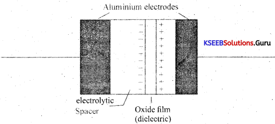
Their capacitance value ranges from 1 pF to 0.01 pF with a voltage, rating of 50V to 10KV. Electrolytic capacitors are suitable for high-frequency applications and in radio frequency and microwave systems.
![]()
Question 5.
Derive an expression for the equivalent capacitance of two capacitors connected in series.
Answer:
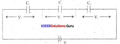
In a series combination, the capacitors are connected end to end. The charge on each capacitor is the same and the emf of the cell equals the sum of voltages across the three resistors. Consider three capacitors C1, C2, C3 connected in series.
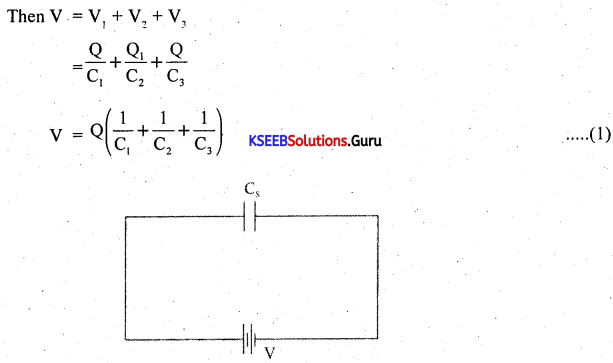
Let the combination be replaced by an equivalent capacitor Cs which has the same effect as the combinations of capacitors. If Cs is the effective capacitance.
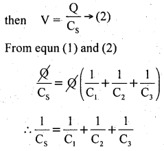
The reciprocal of the effective capacitance of capacitors in series is the sum of reciprocals of individual capacitances.
Question 6.
Derive an expression for the effective capacitance of capacitors connected in parallel.
Answer:
Capacitors are said to be in parallel if they are connected between the same common points. The voltage across each capacitor in parallel is the same.
Let C1, C2 and C3 be the capacitors connected in parallel.
Let V be the applied voltage across the combination.
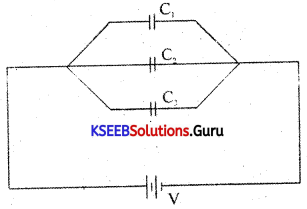
The charge Q from the cell equals the sum of voltages across the capacitors.
Q = Q1 + Q2 + Q3
= C1V + C2V + C3V
Q =V(C1 +C2 + C3) → (1)
The equivalent or effective capacitor is a single capacitor that has the same effect as the combination of capacitors.
If Cp is the effective capacitance then
Q = CpV → (2)
From equations (1) and (2)
CpV = V(C1 + C2 + C3)
Cp = C1 + C2 + C3
Hence, when capacitors are connected in series, the effective capacitance is the sum of individual capacitances.
![]()
Question 7.
Explain the construction and applications of ferrite core inductor and iron core inductor.
Answer:
Ferrite core inductor: In ferrite core inductors, the wire is wound over a solid ferrite core. Ferrite is a synthetic ceramic material that is highly ferromagnetic. Ferrites are insulators that provide high permeability. These have inductance values up to 10mH.
![]()
ferrite core
Ferrite core inductors are used as filter chokes and in TV receivers.
Iron core inductor: In iron core inductors, the coil is wound on a solid laminated iron core. The core is laminated to avoid eddy current losses. A laminated iron core is made up of thin iron laminations pressed together but insulated from each other. These have high inductance values from 1 mH to 1H.
Symbol of iron core inductor
![]()
Symbol of iron core inductor
Iron core inductors are used mainly in audio frequency applications and as filters in DC power supplies and in radio and TV receivers.
Question 8.
Explain the construction and working of the loudspeaker.
Answer:
A loudspeaker is a transducer that changes electrical energy into sound waves of varying pressure.
- a coil of wire called a voice coil.
- a permanent-magnet
- a cone-shaped piece of stiff paper or cloth called the diaphragm.
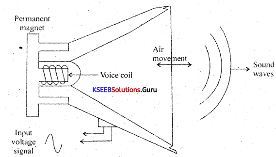
Voice coil is suspended in the strong magnetic field of a circular permanent magnet. The permanent magnet of a speaker provides a steady magnetic field. The two leads of the voice coil are connected with wire to terminals on the speaker frame.
When audio signal current flows through the voice coil, it produces a varying magnetic field in the coil. The varying magnetic field moves the voice coil in and out in accordance with variations in the electrical audio signals. Hence the diaphragm attached to the voice coil vibrates due to which compressions and rarefactions are formed and the sound waves are produced.
![]()
Question 9.
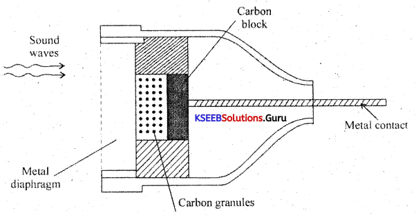
Explain the construction and working of the microphone.
Answer:
The microphone is a device that converts sound energy into an electrical signal. It has an insulating button loosely filled with carbon granules. The button is attached to a very thin steel diaphragm. The diaphragm vibrates when sound waves strike it. Due to vibration, there is variation in the pressure on carbon granules, which changes the resistance of carbon granules in accordance with the pressure of sound waves.
Hence any change in the resistance of carbon granules produces a corresponding change in the current through the circuit. This varying current flowing through the primary coil produces an alternating voltage in the secondary of the transformer.
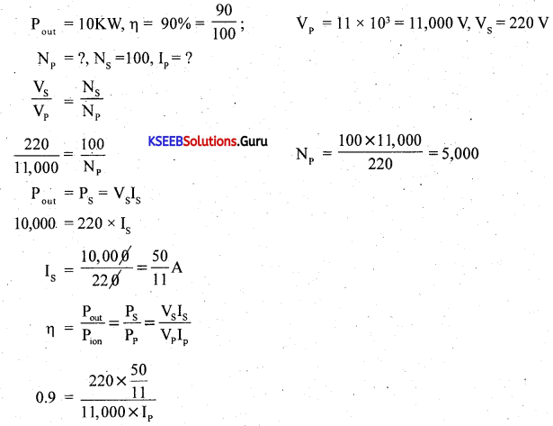
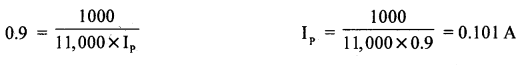
Question 10.
A stepdown transformer having a power output of 10KW and an efficiency of 90% reduces the voltage from 11KV to 220V. Calculate (i) the number of turns in the primary if the secondary has 100 turns and (ii) the current in the primary.
Answer:
Question 11.
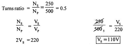
At transformer has 500 turns in the primary and 250 turns in the secondary. What is the turns ratio? How much is secondary voltage with a primary voltage of 220V?
Answer:
Np = 500, Ns = 250
Question 12.
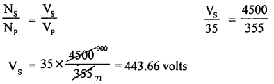
Calculate the voltage output by the secondary winding of a transformer if the primary voltage is 35V, the secondary has 4500 turns and the primary winding has 355 turns.
Answer:
V =?,V = 35V, Ns = 4500, N = 355
![]()
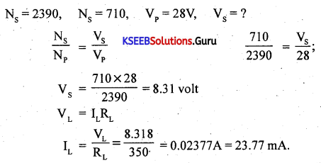
Question 13.
Calculate the load current and load voltage in this transformer circuit.
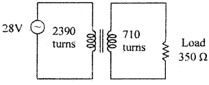
Answer:
Ns = 2390, Ns = 710, Vp = 28V, Vs = ?