Students can Download 2nd PUC Electronics Chapter 5 Operational Amplifiers (OP-Amp) Questions and Answers, Notes Pdf, 2nd PUC Electronics Question Bank with Answers helps you to revise the complete Karnataka State Board Syllabus and score more marks in your examinations.
Karnataka 2nd PUC Electronics Question Bank Chapter 5 Operational Amplifiers (OP-Amp)
2nd PUC Electronics Operational Amplifiers One Mark Questions and Answers
Question 1.
What is a differential amplifier?
Answer:
Differential amplifier is the amplifier which amplifies the difference between the input signals.
Question 2.
What is an Op-amp?
Answer:
OP-amp is a direct coupled high gain amplifier with large bandwidth.
Question 3.
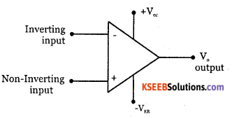
Draw the circuit symbol of Op-amp.
Answer:
Question 4.
List out any two characteristics of an ideal Op-amp.
Answer:
- Infinite input impedance.
- Infinite open loop gain.
![]()
Question 5.
List out any two characteristics of practical Op-amp.
Answer:
- Input impedance is few MΩ
- The open-loop gain is 105.
Question 6.
What are the different kinds of packages of Op-amp?
Answer:
- Mono package.
- Dual package.
Question 7.
Define input off set voltage.
Answer:
Input offset voltage is the small voltage that should be applied between two input terminals to make output voltage zero.
Question 8.
Define CMRR of an Op-amp.
Answer:
CMRR is defined as the ratio of differential mode gain to common mode gain.
Question 9.
Define slew rate.
Answer:
Slew rate is the maximum rate of change of output voltage when a large input signal is given to the closed loop amplifier.
Question 10.
What do you mean by virtual ground with respect to an Op-amp?
Answer:
Zero voltage at the inverting terminal is called virtual ground.
Question 11.
Mention any two linear applications of Op-amp.
Answer:
- Inverting amplifier
- Non-inverting amplifier.
Question 12.
Mention any two non-linear applications of Op-amp.
Answer:
- Differentiator
- Integrator.
Question 13.
What is an integrator?
Answer:
Integrator is a circuit whose output is proportional to intergral of its input.
![]()
Question 14.
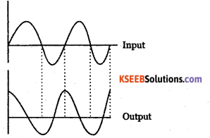
Sketch the output of an integrator if input is a sin wave.
Answer:
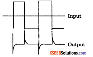
Question 15.
Sketch the output of an integrator if input is a square wave.
Answer:
Question 16.
What is logarithmic amplifier?
Answer:
Logarithmic amplifier is a circuit whose output is proportional to natural logarithm of the input voltage.
Question 17.
What is an active filter?
Answer:
Active filters are circuits which make use of passive components such as resistors and active components such as op-amp for the selection of band of frequencies.
Question 18.
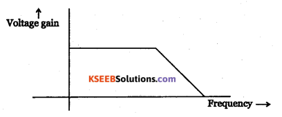
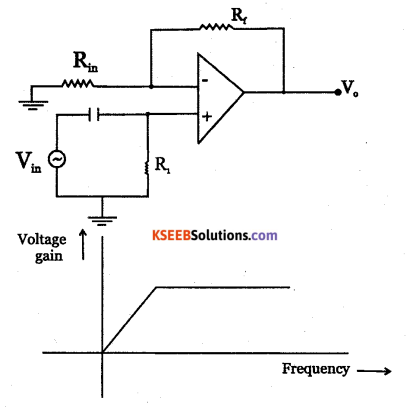
What is a first-order low pass active filter?
Answer:
It is a single-stage RC filter circuit followed by an op-amp non-inverting amplifier.
Question 19.
What is a second-order low pass active filter?
Answer:
It is a two-stage RC filter circuit followed by an op-amp non inverting amplifier.
![]()
Question 20.
Write any one application of logarithmic amplifier.
Answer:
It is used to multiply two input signals.
Question 21.
What is a digital to analog converter?
Answer:
A digital to analog converter is used for conversion of digital input into an analog output.
Question 22.
What is analog to digital converter?
Answer:
An analog to digital converter is used for conversion of an analog input into a digital ouput.
Question 23.
Name any open loop application of an op – amp.
Answer:
Comparator.
Question 24.
What is Comparator?
Answer:
Comparator compares one input of the op-amp with the other input of the op-amp.
Question 25.
Name any one application of Schmitt Trigger?
Answer:
Schmitt Trigger is used to convert any periodically varying signal into a square wave.
2nd PUC Electronics Operational Amplifiers Two Marks Questions and Answers
Question 1.
Name four modes of differential amplifiers.
Answer:
- Dual input and balanced output differential amplifier.
- Single input and single output differential amplifier.
- Dual input and unbalanced output differential amplifier.
- Single input and balanced output differential amplifier.
![]()
Question 2.
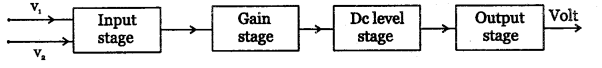
Draw block diagram of op-amp.
Answer:
Question 3.
Define slew rate of an op-amp.
Answer:
Slew rate of an op-amp is the maximum rate of change of output voltage when a large input signal is given to the closed-loop amplifier.
Question 4.
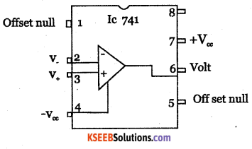
Draw the pin configuration of IC741.
Answer:
Question 5.
Explain virtual ground concept with respect to op amp.
Answer:
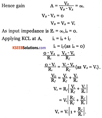
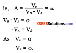
If VA and VB are the voltages at inverting and non-inverting terminals, then open-loop gain.
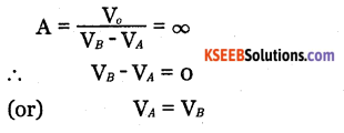
As VB = 0 (as non-inverting terminal is grounded), VA=0.
Zero voltage at the inverting terminal is called virtual ground.
Question 6.
What are the assumptions made for ideal op-amp characteristics?
Answer:
Infinite open-loop gain, Infinite bandwidth, Infinite input impedance, Zero output impedance, infinite CMRR.
Question 7.
Mention some of the linear applications of op-amp.
Answer:
Inverting amplifier, non-inverting amplifier, op-amp summing amplifier, op-amp subtractor.
![]()
Question 8.
Mention some of non-linear applications of op-amps.
Answer:
Differentiator, Integrator, logarithmic amplifier.
Question 9.
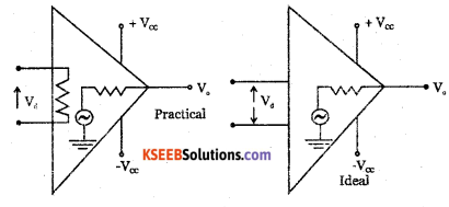
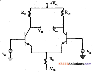
Explain how an ideal op-amp different from a practical op-amp?
Answer:
| Characteristics | Ideal op amp | Practical op – amp |
| open loop gain | ∞ | 105 |
| Input impedance | ∞ | Few M Ω. |
| Output impedance | 0 | Few ohm. |
| Bandwidth | ∞ | Few MHz. |
| CMRR | ∞ | 90 dB |
Question 10.
The gain of a buffer amplifier is unity. Explain.
Answer:
Op amp buffer amplifier is a non-inverting amplifier where output terminal and the inverting input terminal are shorted.
Question 11.
List parameters of an ideal op amp and also write its values for 741 op amp.
Answer:
| Characteristics | Ideal op amp | Practical op amp |
| open-loop gain | ∞ | 105 |
| Input impedance | ∞ | Few M Q. |
| Output impedance | 0 | Few ohm. |
| Bandwidth | ∞ | Few MHz. |
| CMRR | ∞ | 90 dB |
| Slew rate | ∞ | o.5v/ ps |
| Input offeset voltage | 0 | Few mV. |
![]()
Question 12.
How can you use an op-amp to invert a signal?
Answer:
A signal can be inverted if it is applied to the inverting input terminal of the op-amp.
Question 13.
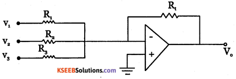
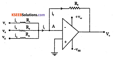
Draw the circuit diagram of a three input summing amplifier.
Answer:
Question 14.
Draw the circuit diagram of a subtractor.
Answer:
Question 15.
Draw the circuit diagram of a logarithmic amplifier.
Answer:
Question 16.
Draw the circuit diagram of an antilogarithmic amplifier.
Answer:
Question 17.
Name any two types of digital to analog converter.
Answer:
- R-2R ladder network.
- Binary weighted resistor.
![]()
Question 18.
Draw the block diagram of a binary-weighted resistance DAC.
Answer:
Question 19.
Draw the block diagram of the counting analog to digital converter.
Answer:
Question 20.
What is a zero crossing detector?
Answer:
Zero crossing detector is a circuit whose output voltage switches its state. This circuit can be used to convert sine waveform to square waveform.
Question 21.
How can you use an op amp as a comparator?
Answer:
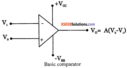
If a reference voltage V is given to one of the terminals and a varying signal to the other terminal, the comparator compares the varying signal with Vref and generates a digital output with two voltage states +Vsat and -Vsat.
Question 22.
What is a Schmitt trigger?
Answer:
It is a comparator which compares the varying input signal with positive feedback voltage. It is used to convert any periodically varying signal into a square wave.
2nd PUC Electronics Operational Amplifiers Three Marks Questions and Answers
Question 1.
Draw and explain the block diagram of an op-amp.
Answer:

- Input stage is a diffrential amplifier which provides high CMRR, high input impedance and high voltage gain. The two input, are inverting and non-inverting input.
- Gain stage further increases the voltage gain of the input stage.
- DC level shifter will bring back the quiscent voltage to original level.
- Output stage is a complementary symmetry push-pull amplifier which has low output amplifier.
![]()
Question 2.
Draw the ac equivalent circuit of op-amp.
Answer:
Question 3.
Write any three differences between ideal and practical op-amps.
Answer:
| Characteristics | Ideal opamp | Practical op-amp. |
| Input impedance | Infinity | few MQ. |
| Output impedance | 0 | few ohm. |
| Bandwidth | Infinity | few MHZ. |
Question 4.
Draw an inverting amplifier using an op-amp and derive the expression for its output. voltage.
Answer:
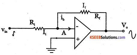
The output of op-amp inverting amplifier is 180° out of phase with respect to its input.
Question 5.
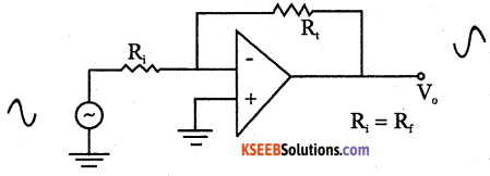
Draw a non-inverting amplifier using op-amp and derive expression for its output voltage.
Answer:
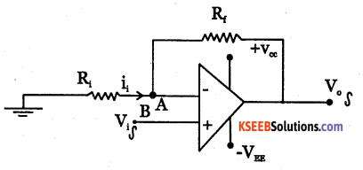
Non-inverting amplifier is the amplifier whose output is in phase with the input.
For an ideal ap – amp,open loop gain, A = ∞
Question 6.
Show that on operational amplifer can be used as an inverting adder.
Answer:
Thus, an operational amplifier can be used as an inverter adder.
![]()
Question 7.
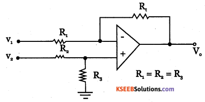
Show how an operational amplifier can be used as a subtractor.
Answer:
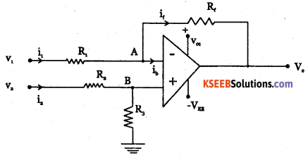
Op – amp as subtractor.
The output voltage V0 = V2 – V1
Question 8.
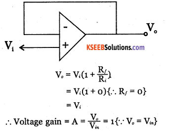
What do you understand by unity gain voltage follower? Explain its gain term with a neat circuit diagram
Answer:
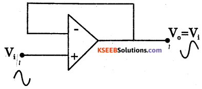
Voltage follower is Obtained by shorting Rf. The output is directly fed to inverting input terminal. Output voltage V of non-inverting
It is used as buffer amplifier for impedance matching.
Question 9.
Explain how an operational amplifier can be used as an integrator.
Answer:
Integrator is a circuit whose output is proportional to integral of its input.
![]()
Question 10.
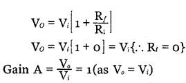
Explain how an op -amp can be used as a differentiator
Answer:
Differentiator is a circuit whose output is proportional to derivative of its input.
Question 11.
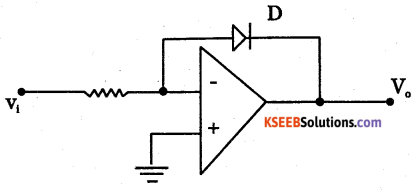
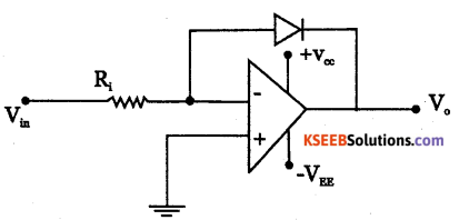
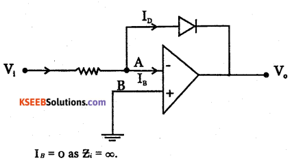
Show the circuit diagram by which we can obtain an output which is logarithm of the input.
Answer:
Question 12.
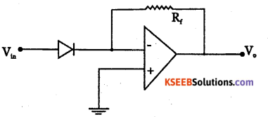
Show the circuit diagram by which we can obtain an output which is antilogarithm of the input.
Answer:
Question 13.
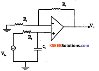
Draw the circuit diagram, frequency response and expression for cut off frequency for a first-order RC low pass active filter.
Answer:
![]()
Question 14.
Draw the circuit diagram, frequency response and the expression for the cut frequency for first-order RC high pass filter.
Answer:
Question 15.
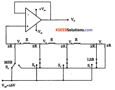
Draw a neat diagram of 4 bit R -2R ladder network DAC
Answer:
Question 16.
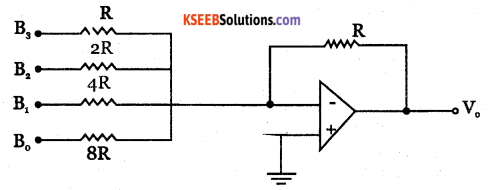
Explain with a neat circuit diagram the working of a binary weighted resistance DAC.
Answer:
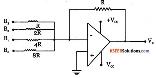
The weighed resistors are connected to a summing amplifier to get output voltage. The output voltage is proportional to the digital inputs.
Question 17.
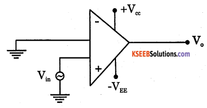
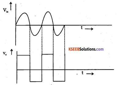
Explain Zero crossing detector with circuit diagram and waveforms.
Answer:
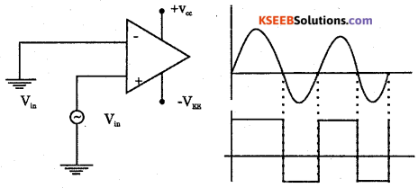
The time-varying signal is applied to the non-inverting terminal and the inverting terminal is grounded. Every time Vn crosses Zero, V0 switches its state. This circuit can be used to convert sinewave form into a square waveform.
![]()
Question 18.
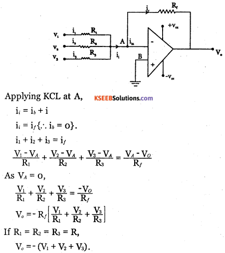
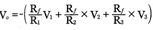
Show how an operational amplifier can be used as a perfect adder.
Answer:
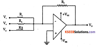
The output voltage V0 = – (V1 + V2 + V3)
2nd PUC Electronics Operational Amplifiers Five Marks Questions and Answers
Question 1.
What is a differential amplifier? Draw four modes of differential amplifier.
Answer:
Differential amplifier is a circuit which amplifies the difference of inputs applied to it.
Dual input and balanced output differential Amplifier
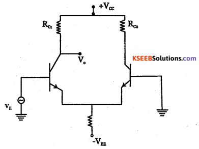
Single input and unbalanced output differncial amplifier
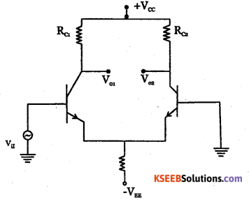
Single input and balanced output differncial amplifier
Dual input and unbalanced output differential Amplifier
![]()
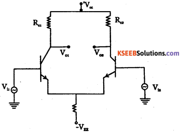
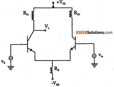
Question 2.
Explain with a neat circuit diagram, the working of dual input balanced output differential amplifier.
Answer:
Dual input balanced output differential amplifier. The working of dual input balanced output differential amplifier can be analysed using superposition theorem.
Case(i): Consider Vn while grounding VB. Vn is input to transistor Q1 at base and output Vo| is taken at the collector and hence Q1 acts as CE amplifier. V1 is out of phase with respect to Vn. Q2 acts as CB amplifier as input voltage V1 which appears at emitter of Q2 gets amplified and obtained at collector of Qr V2 is in phase with V…
Case(ii): Consider V2, while grounding V1 .va is input to transistor Q2 which acts as CE amplifier. The amplified output V02 is out of phase with respect to input voltage V12 which appears at emitter of Q, gets amplified and obtained at collector of Q, as V01 which is in phase with Vi2.
When both the input signals Vi1 and Vi2 are applied, the output voltage V0 is measured between two collectors and voltage gain
\(A_{v}=\frac{V_{0}}{V_{i 1}-V_{i 2}}\)
Question 3.
What is operational amplifier? Write the properties of ideal op-amp and also draw its AC equivalent circuit.
Answer:
The operational amplifier is a direct-coupled high gain high bandwidth amplifier
| Characteristics | Ideal op amp |
| open loop gain | ∞ |
| Input impedance | ∞ |
| Output impedance | 0 |
| Bandwidth | ∞ |
| CMRR | ∞ |
| Stew rate | ∞ |
| Input offset voltage | 0 |
Question 4.
Compare the following terms relaled to a pratical op -amp in brief with respect to ideal op – amp.
(a) Bandwidth
(b) Slew rate
(c) Input offset voltage
(d) Common mode rejection ratio
(e) Open loop gain.
Answer:
| Characteritics | Ideal op amp | Practical op-amp. |
| Bandwidth | ∞ | Few MHZ |
| Slew rate | ∞ | 0.5V/us. |
| Input offset voltage | 0 | Few mV. |
| CMRR | ∞ | 90 dB. |
| Open loop gain | ∞ | 10 |
![]()
Question 5.
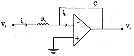
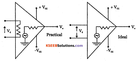
Explain virtual ground concept and also derive an expression for the output of an inverting adder.
Answer:
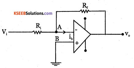
Even though the inverting terminal is not grounded ,there exists Zero voltage at A Hence A is called virtual ground.
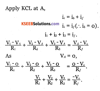
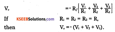
The output is negative sum of input voltages.
Question 6.
With circuit diagram, show how to obtain an expression for the output which is logarithm of input
Answer:
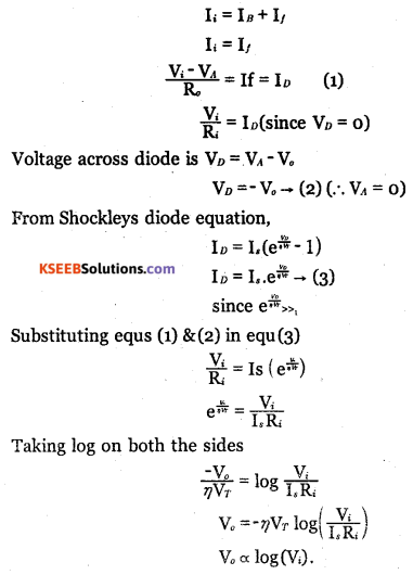
∴ The output voltage is proportional to natural logarithm of input voltage.
![]()
Question 7.
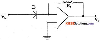
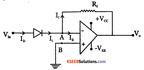
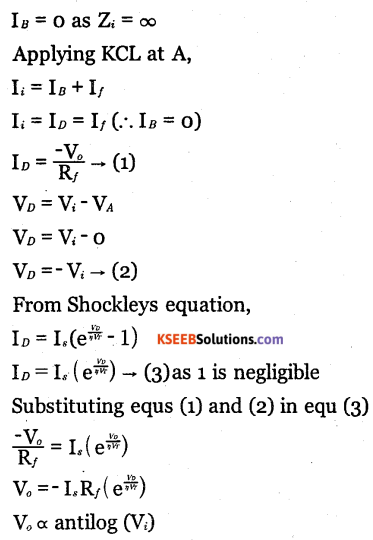
With circuit diagram, show how to obtain an output which is anti logarithm of input.
Answer:
Question 8.
With circuit diagram, show how to obtain an output which is multiplication of two input signals.
Answer:
Logarithmic and anti-logarithmic amplifiers are used to multiply two input signals.
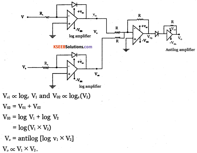
Thus, the final output obtained is proportional to the multiplication of two input signals.
Question 9.
What do you understand by filters? Give its classification Draw the circuit diagram, frequency response and expression for the cut off frequency for a first order RC low pass filter.
Answer:
Filter are circuits used to select a band of frequencies. The two types of filters are
- low pass filter and
- high pass filter.
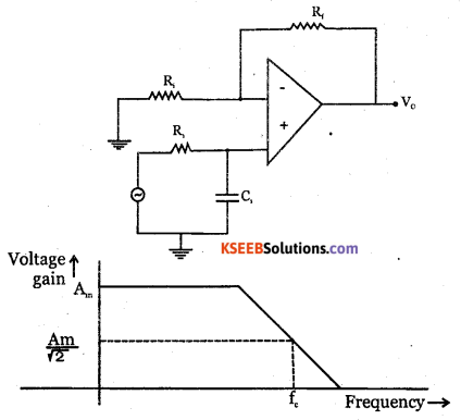
Cut off frequency \(\mathrm{f}_{C}=\frac{1}{2 \Pi \mathrm{R}_{1} \mathrm{C}_{1}}\)
Frequency response of low pass filter
![]()
Question 10.
With a neat diagram, explain the working of 4 bit R-2R ladder network DAC.
Answer:
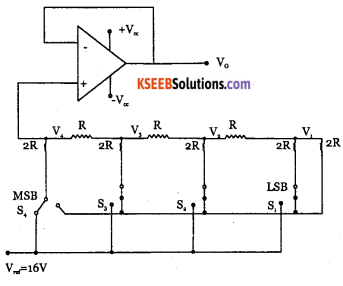
The ladder network has R and 2R connected as shown. The binary inputs are switches which can be connected to either Vref = 16V (logic 1) or OV (logic 0).
The output voltage Vout is generated depending on the input voltages at the switches.
Using superposition theorem, output voltage generated for more than one switch at logic 1 is addition of voltages due to the individual switches.
The voltage developed at the output of ladder network is proportional to the binary inputs. This voltage is fed to the voltage follower circuit using op-amp and V ut is obtained.
Question 11.
With a block diagram and waveforms, explain the working of the counting analog to digital converter.
Answer:
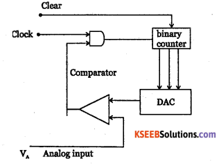
This type of ADC has a comparator, binary counter, DAC and AND gate.
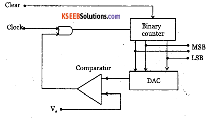
The counter is reset to Zero count by the clear pulse. The counter counts based on number of pulses received by the clock signal. The binary output of counter is used as input to digital to analog converter, whose output is staircase waveform, is continuously compared with analog input signal by the comparator.
If analog input VA is greater than output V0 of DAC, the comparator produces a high signal. This makes AND gate open for transmission of clock pulses to the counter.
If DAC output exceeds the analog input VA, the comparator generates a low signal and AND gate is disabled. This stops the counter when VA = V0 and the output of the counter is the digital equivalent to the analog input voltage.
Question 12.
With neat circuit diagrams and waveforms explain the applications of a comparator.
Answer:
The two applications of comparator are Zero crossing detector.
A time-varying signal is applied to the non-inverting terminal, and inverting terminal is grounded.
If Vin > 0,V0 = + Vsat
If Vin < 0,V0 = + Vsat
Every time Vin crosses Zero level, V switches its state. Hence it is called Zero crossing detector. It is also used to convert a sine waveform to a square waveform. Input and output waveforms of Zero crossing detector.
2. Schmitt Trigger
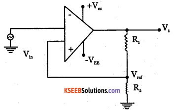
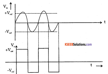
The reference voltage Vref is a fraction of the output voltage which id feedback to
non – inventing terminal
If Vin >Vref,V0 = + Vsat
If Vin < Vref,V0 = + Vsat
This circuit does not respond to triggering due to the noise. Schmitt trigger can be used to convert any periodically varying signal into a square wave.
![]()
Problems with Solutions
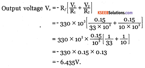
Question 1.
Calculate output voltage if V1 = V2 = 0.15V.
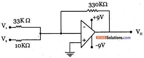
Answer:
Question 2.
Determine output voltage when V1 = -V2 = 1V.
Answer:
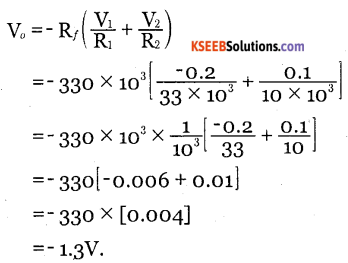
Question 3.
Calculate the output voltage if V1 = -0.2V and V2 = 0.1V.
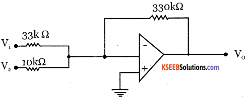
Answer:
![]()
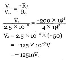
Question 4.
Determine the output voltage for this circuit when a sinusoidal input of 2.5 mV is applied.
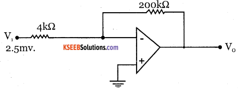
Answer:
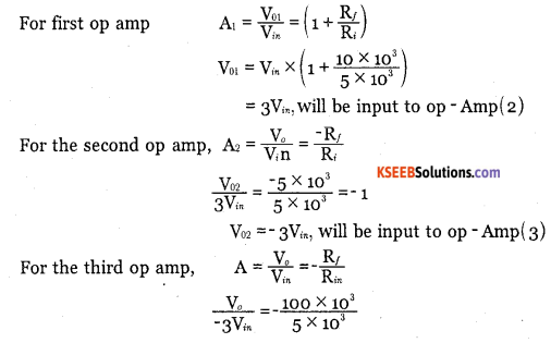
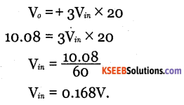
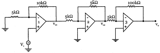
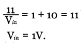
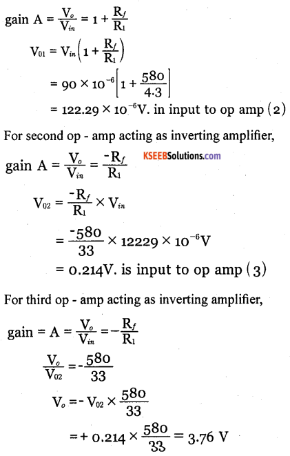
Question 5.
Calculate the input voltage if the final output is 10.08V
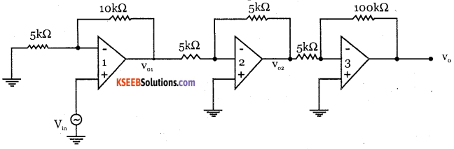
Answer:
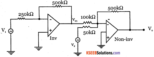
Question 6.
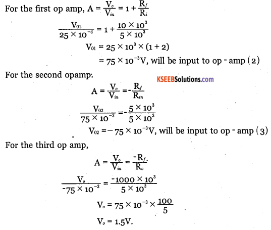
Calculate the output voltage of the following circuit when V = 25m V?
Answer:
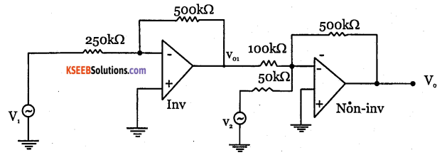
Question 7.
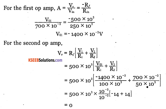
Calculate the output voltage if V1 = V2 = 700mV.
Answer:
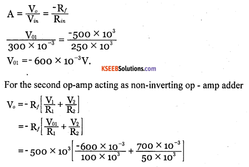
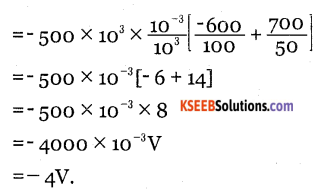
Question 8.
Calculate output voltage if V1= 300 mV, V2 = 700mV.
Answer:
![]()
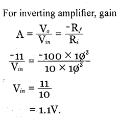
Question 9.
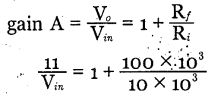
Calculate the input voltage for this circuit if V0 = -11V.
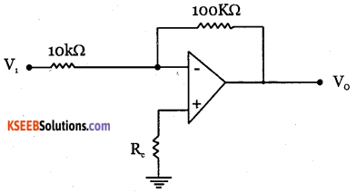
Answer:
Question 10.
Calculate the input voltage when Vn = 11V.
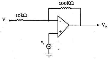
Answer:
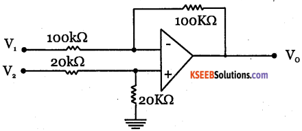
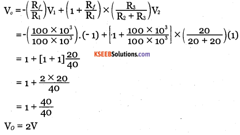
Question 11.
Calculate the output voltage.
Answer:
![]()
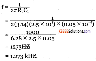
Question 12.
Calculate cut-off frequency of a first order low pass filter for R1= 2.5KΩ C1 = 0.05μF.
Answer:
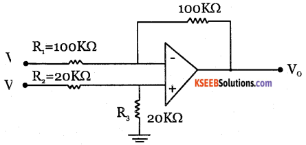
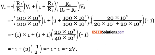
Question 13.
Determine the output voltage when V1 = -V2 = – 1 V.
Answer:
Question 14.
How many op-amps are required to implement this equation:
Answer:
One op-amp.
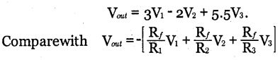
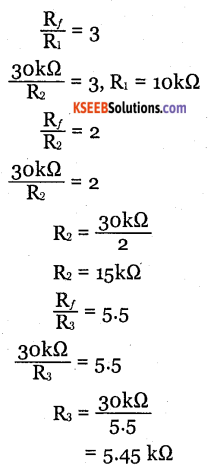
Question 15.
The output of an op-amp adder is to be V0 = 3V1 – 2V2 + 5.5V3 If the value of the feedback resistor is 30kΩ, find the values of R1, R2 and R3
Answer: