Students can Download 2nd PUC Electronics Chapter 8 Modulation and Demodulation Questions and Answers, Notes Pdf, 2nd PUC Electronics Question Bank with Answers helps you to revise the complete Karnataka State Board Syllabus and score more marks in your examinations.
Karnataka 2nd PUC Electronics Question Bank Chapter 8 Modulation and Demodulation
2nd PUC Electronics Modulation and Demodulation One Mark Questions and Answers
Question 1.
What is modulating signal?
Answer:
Modulating signal is the low frequency information signal which changes the high frequency carrier wave.
Question 2.
What is carrier wave?
Answer:
Carrier wave is the high frequency wave on which audio signal is superimposed to transmit to large distances.
Question 3.
What is modulation?
Question Answer:
Modulation is the process by which one of the characteristics of a high frequency carrier wave is changed in accordance with the instantaneous value of a low frequency information signal.
![]()
Question 4.
How is the length of antenna related to frequency of the signal?
Answer:
The length of the antenna required for transmission is inversly proportional to the frequency of the signal.
\(\left\{ { L }=\frac { \lambda }{ 4 } =\frac { { C } }{ 4{ f } } \quad \lambda =\frac { { C } }{ 4{ f } } \right\} \)
Question 5.
Define amplitude modulation.
Answer:
Amplitude modulation is the process in which amplitude of the carrier wave is varied in accordance with instantaneous value of the modulating signal.
Question 6.
Write the expression for instantaneous voltage of an AM wave.
Answer:
Ym = Vc (1+ masinwmt). sin wc t
![]()
Question 7.
Define modulation index of an AM wave.
Answer:
Modulation index of an AM wave is the ratio of amplitude of modulating signal (Vm) to the amplitude of the carrier signal (Vc).
Question 8.
Define percent modulation for an AM wave.
Answer:
Percent modulation for an AM wave is its modulation index multiplied by 100.
Question 9.
How many side bands are present in AM?
Answer:
Two.
Question 10.
What is the bandwidth of AM wave?
Answer:
The frequency range occupied by the AM wave which is twice the modulating signal frequency.
Question 11.
Mention the expression for the modulation index in terms of Vmax and Vmin.
Answer:
\(\mathrm{m}_{a}=\frac{\mathrm{V}_{\max }-\mathrm{V}_{\min }}{\mathrm{V}_{\max }+\mathrm{V}_{\min }}\)
Question 12.
What happens when modulation index exceeds unity?
Answer:
When modulation index exceeds unity, the envelope of the output is distorted.
Question 13.
What is over modulation?
Answer:
When modulation index exceeds unity, the envelope of the output waveform gets distorted and this is known as over modulation.
Question 14.
Write the expression for power of AM wave.
Answer:
\(\mathrm{P}_{T}=\mathrm{P}_{C}\left[1+\frac{\mathrm{m}_{a}^{2}}{2}\right]\)
![]()
Question 15.
Which are the components of AM wave carrying information?
Answer:
- Upper side band
- Lower side band.
Question 16.
What is the power present in each side band in AM, when ma = 1
Answer:
The power in each sideband in AM when ma= 1 is one sixth of total power of AM wave.
Question 17.
Define efficiency of transmission.
Answer:
Transmission efficiency of an AM wave is the ratio of power contained in the sidebands to the total power.
Question 18.
What is total modulation index when a carrier wave is modulated by a number “of sinewaves.
Answer:
Total modulation index:
Question 19.
Why is transmission of side bands important?
Answer:
As the side bands contain the required signal, their transmission is important.
\(\mathrm{m}=\sqrt{\mathrm{m}_{1}^{2}+\mathrm{m}_{2}^{2}+\mathrm{m}_{3}^{2}+\ldots \ldots \mathrm{m}_{n}^{2}}\)
Question 20.
What is DSB-SC?
Answer:
DSB-SC is double side band-suppressed carrier.
![]()
Question 21.
What is SSB-TC?
Answer:
Single side band transmitted carrier.
Question 22.
What is SSB-SC?
Answer:
Single side band suppressed carrier.
Question 23.
Define low level modulation.
Answer:
Low level modulation is generating AM wave with small signal which must be amplified before transmission.
Question 24.
Define high level modulation.
Answer:
High level modulation is generating AM wave with high power levels in the final stage of transmission.
Question 25.
Define frequency modulation.
Answer:
Frequency modulation is the process of varying frequency of carrier wave in accordance with the instantaneous value of modulating signal.
![]()
Question 26.
Define angle modulation.
Answer:
The frequency and phase modulation together is called angle memulation.
Question 27.
Define phase modulation.
Answer:
Phase modulation is the process of varying phase of the carrier wave in accordance with instantaneous value of modulating signal.
Question 28.
What is resting frequency?
Answer:
Frequency of carrier wave in FM is called the resting frequency.
Question 29.
Write the expression for instantaneous voltage of frequency modulated wave.
Answer:
VAM = Vc sin(wct +mf sin wmt).
Question 30.
Define modulation index of FM.
Answer:
Modulation index is the ratio of maximum frequency deviation to the modulation signal frequency.
Question 31.
Define percent modulation for FM wave.
Answer:
Percent modulation of FM wave is the ratio of carrier frequency deviation to the maximum carrier frequency deviation.
![]()
Question 32.
Define frequency deviation.
Answer:
Frequency deviation is the change in carrier frequency produced by the modulating signal from its centre frequency.
Question 33.
Define deviation ratio.
Answer:
Deviation ratio is the ratio of maximum allowed frequency deviation to the maximum frequency of modulating signal.
Question 34.
What are guard bands?
Answer:
Guard band is the range of frequencies added on either side of channel width to prevent interfemce between adjacent channels.
Question 35.
How many side bands are present in FM wave?
Answer:
Infinite side bands.
Question 36.
What are significant side bands?
Answer:
Significant side bands are the sidebands having amplitude more than or equal to 1% of carrier amplitude.
Question 37.
Define carrier swing.
Answer:
Carrier swing is the total variation in frequency from minimum to maximum value.
Question 38.
What is bandwidth of a FM station?
Answer:
Bandwidth of FM wave is defined as width of the frequency spectrum that contains all side frequency components haveing amplitude equal to or greater than one percent of the amplitude of the carrier.
![]()
Question 39.
What is the maximum permitted frequency deviation in FM?
Answer:
75 kHz.
Question 40.
State Carsons rule of FM bandwidth.
Answer:
According to Carsons rule, bandwidth is twice the sun of maximum frequency deviation and highest modulating frequency.
Question 41.
Which is better for high fidelity reception FM or AM?
Answer:
Frequency modulation.
Question 42.
Which is better for high sensitivity reception FM or AM?
Answer:
FM.
Question 43.
What is pre-emphasis?
Answer:
Pre-emphasis is the process of boosting relative amplitudes of high frequency components of the modulating signal to improve signal to noise ratio.
Question 44.
What is de-emphasis?
Answer:
De-emphasis is the process of attenuating the relative amplitude of high frequency components of the modulating signal.
Question 45.
Define demodulation.
Answer:
Demodulation is the process of recovering a modulating signal from the modulated wave.
![]()
Question 46.
What is an envelop detector?
Answer:
Diode detector is also called envelop detector.
Question 47.
Difine sensitivity.
Answer:
Sensitivity of a radio receiver is its ability to.respond to weak signals.
Question 48.
Define selectivity.
Answer:
Selectivity is the ability of a radio receiver to distinguish between desired signal to which the receiver is tuned and the other signal frequencies.
Question 49.
Define fidelity.
Answer:
Fidelity of a radio receiver is its ability to reproduce faithfully in its output, the signal that appears at its input.
Question 50.
Define heterodyning?
Question Answer:
Heterodyning is the process of mixing or beating together two signals of different frequencies to produce a set of new frequencies.
Question 51.
What is intermediate frequency?
Answer:
Intermediate frequency is the difference of frequencies of local oscillator and carrier frequencies.
Question 52.
Mention the value of IF for AM reception.
Answer:
455 kHz.
Question 53.
Mention the value of IF for FM reception.
Answer:
10.7 MHz.
![]()
Question 54.
What is the purpose of limiter in an FM receiver?
Answer:
The limiter keeps IF amplifer output voltage constant.
Question 55.
Define image frequency.
Answer:
Image frequency is the undesired input frequency equal to station frequency plus twice the intermediate frequency.
Question 56.
What are transmission lines?
Answer:
Transmission lines are the material structure used for transport of electrical signals or energy from one location to another far off destination.
Question 57.
What are antennas?
Answer:
Antenna is a device that is used to radiate and receive electromagnetic waves.
Question 58.
What is the purpose of using transmission lines in communication?
Answer:
They are used for transport of electrical signals from one location to another far off destination.
Question 59.
Write .one application of Helical antenna.
Answer:
Helical antenna are used at earth base stations in satellite communication.
Question 60.
What ‘yagi’ stand for in yagi antenna.
Answer:
Yagi is used to describe type of antenna and is credited to famous Japanese antenna experts Yagi and Uda.
Question 61.
What is Horn antenna?
Answer:
It is an antenna consisting of a flaring metal waveguide shaped like a horn to direct radio waves in a beam.
![]()
Question 62.
Which type of antenna is used in small electronic devices?
Answer:
Microstrip antenna.
Question 63.
Which frequency signals are processed by a microstrip antenna?
Answer:
ultra high frequencies (300 MHz to 3 GHz).
Question 64.
What is digital communication?
Answer:
Digital communication is a mode of communication where the information is encoded digitally as discrete signals and electronically transferred to the receipients.
2nd PUC Electronics Modulation and Demodulation Two Marks Questions and Answers
Question 1.
What is the need for modulation?
Answer:
Modulation is needed
- to reduce length of antenna
- to increase operating range
- for wireless communication and
- to reduce interference.
Question 2.
Mention different types of modulation.
Answer:
- Amplitude modulation.
- Frequency modulation.
- Phase modulation.
Question 3.
What is angle modulation? Which are different types of angle modulation?
Answer:
In angle modulation, total angle φ = wct + θ of the carrier wave is varied. Different types of angle modulation are
- Frequency modulation.
- Phase modulation.
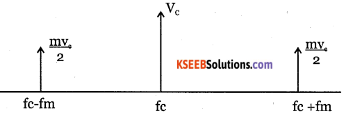
Question 4.
Draw the frequency spectrum of an AM wave
Answer:
Question 5.
Define modulation index for an AM wave. What is its significance?
Answer:
Modulation index of AM wave is the ratio of amplitude of modulating signal (Vm) to the amplitude of the carrier wave (Vm) It indicates the depth of modulation.
Question 6.
Define transmission efficiency and state its relation with in.
Answer:
Transmission efficiency is the ratio of power contained in the sideband to the total power.
Transmission efficiency, \(\eta=\frac{\mathrm{m}_{a}^{2}}{2+\mathrm{m}_{a}^{2}}\)
Question 7.
What are applications of AM?
Answer:
AM is used for broadcasting:
- Radio on long medium and short waves.
- TV picture in ultra short waves.
- Radio telephony on short waves.
Question 8.
Why is transmission of sideband important in AM?
Answer:
The sideband transmission is important in AM because it contains the information signal.
![]()
Question 9.
What are advantages of SSB system over conventional DSB system?
Answer:
- Power saving is 83.3%
- Operating cost is less.
- Reduced interference of noise.
- Requires only small power supply.
Question 10.
What are disadvantages of single sideband transmission?
Answer:
- generation and reception of SSB signal is complicated.
- The SSB requires more complex and expensive transmitter and the receiver.
Question 11.
Distinguish between low level and highlevel modulations.
Answer:
Low level modulation is generating AM wave with small signal which must be amplified before transmission. High level modulation is generating AM wave with high power levels in the final stage of transmitter.
Question 12.
Why is AM transmission noisy?
Answer:
A radio receiver can not distinguish between the amplitude variations representing noise and those containing the desired signal. Different types of atmospheric and other electrical disturbances are reproduced in AM receivers. Hence AM reception is noisy.
Question 13.
What is the purpose of guard bands in broadcast FM? How wide is the FM broadcast channel?
Answer:
The purpose of guard bands is to prevent interference between adjacent channals. The width of FM broadcast channel is 200 kHz.
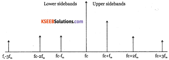
Question 14.
Draw frequency spectrum of FM wave
Answer:
Question 15.
What is the use of a buffer amplifer stage in a transmitter?
Answer:
Buffer amplifier isolates crystal oscillator and the power amplifier, so that frequency of ac signal produced does not vary.
Question 16.
What are pre-emphasis and de-emphasis?
Answer:
Pre-emphasis is the process of boosting the relative amplitude of high frequency components of the modulating signal. De-emphais is the process of attenuating the relative amplitudes of high frequency components of the modulating signal.
![]()
Question 17.
Write a short note on demodulation of AM wave.
Answer:
Demodulation is the process of separating the audio signal from AM wave. It is done in a superheterodyne receiver.
Question 18.
Which are different types of AM dectors?
Answer:
- Diode detector.
- Superheterodyne detector.
Question 19.
Mention the advantages of diode detector.
Answer:
- It can handle large input signals.
- It is highly efficient.
- It produces dc voltage for automatic gain control.
- It rectifies with minimum distortion.
Question 20.
Mention the advantages of quadrature detector.
Answer:
- It offers good level of performance.
- It can be incorporated into an ac.
- It can operate even for small amplitude signals.
Question 21.
What are the basic functions of radio receivers?
Answer:
- Intercept incoming modulated signal.
- select desired frequency.
- Amplify selected modulated carrier.
- Detect modulating signal.
- Amplify modulating frequency signal.
- Convert AF signal into corresponding sound signal.
Question 22.
What are the characteristics of a good receiver?
Answer:
- Selectivity
- Sensitivity
- Fidelity
- Signal to noise ratio.
- Stability
Question 23.
What is the need for intermediate frequency?
Answer:
As IF is much lower than RF input signal, the IF amplifiers are easier to design and to obtain good selectivity with tuned circuits.
Question 24.
What are the characteristics of a good receiver?
Answer:
- Selectivity
- Sensitivity
- Fidelity
- Signal to noise ratio.
- Stability
Question 25.
What do you mean by AGC? Why is it necessary for a receiver?
Answer:
The process of maintaining a constant output at a receiver regardless of variations in the input signal strength is called automatic gain control. AGC is required to reduce the noise and to maintain a constant output.
![]()
Question 26.
What are advantages of superheterodyne receiver?
Answer:
It has very high sensitivity and selectivity and easier to tune over wide frequency range.
Question 27.
What is the purpose of AFC loop? Why is it necessary for a receiver?
Answer:
AFC is used to correct unever frequency drift at the output. It is necessary to stabilise the carrier frequency.
Question 28.
What is the purpose of a discriminator in an FM broadcast receiver?
Answer:
Discriminator recovers modulating signal from the IF signal. It converts received FM signals into proportional AM and then detects AM for the recovery of modulating signal.
Question 29.
Describe basic differences between AM and FM receivers.
Answer:
| AM receiver | FM receiver |
| 1. It does not have limiter 2. It does not have discriminator. 3. Pre-emphasis and de-emphasis not done. |
1. It has a limiter. 2. It has discriminator. 3. Pre and de-emphasis are done. |
Question 30.
Write the advantages of FM over AM?
Answer:
- All transmitted power is useful.
- Signal to noise ratio is very high.
- Fidelity is very high.
- Noise can be completely eliminated.
Question 31.
What are the disadvantages of FM system?
Answer:
- Bandwidth is very large.
- Range of transmission is small.
- FM transmitters and receivers are more complex.
![]()
Question 32.
What are applications of AM?
Answer:
- Radio on long, medium and short waves.
- Radio telephony on short waves.
- TV picture on very short waves.
Question 33.
What are primary constants of transmission lines?
Answer:
Primary constants of transmission lines are:
- Series resistance (R)
- Series inductance (L)
- Shunt capacitance (C)
- Shunt conductance (G)
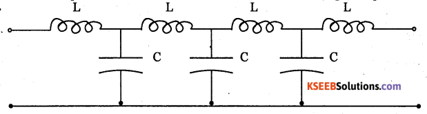
Question 34.
Draw the equivalent circuit of transmission lines, for radio (high) frequencies.
Answer:
Question 35.
Write any two applications of transmission lines.
Answer:
Transmission lines are used as:
- Filters
- Pulse generators
- Impedance transformers.
- Transmitter of high frequency signals with minimum loss.
Question 36.
Write a note on antennas.
Answer:
Antenna is a device used to radiate and receive electromagnetic waves. They are required for transmission of TV programs, satellite broadcasts, radio broadcasts and for cellular telephone communications.
Question 37.
Mention any two types of antennas.
Answer:
- Yogi antenna.
- Helical antenna.
Question 38.
Briefly in explain Yagi antenna?
Answer:
Yagi antenna is called so in memory of Japanese antenna experts Yagi and Uda. It is an array of parallel, straight antenna elements.
![]()
Question 39.
Write any two applications of Horn antennas.
Answer:
- Horn antennas are used as feeders for parabolic antennas.
- They are active elements in dish antennas.
Question 40.
Mention any two uses of microstrip antenna.
Answer:
- They are used to process UHF signals.
- They are used as a satellite radio or cell phone receiver.
Question 41.
Why is digital communication preferred over analog communication?
Answer:
Digital communication is preferred because:
- It is quickest and most reliable mode of communication.
- It is cheapest mode of transmission.
Question 42.
Mention advantages of using digital communication over analog communication?
Answer:
Digital communication is preferred over analog communication because:
- It is quickest and most reliable mode of communication.
- It is cheaper mode of transmission than analog communication.
Question 43.
Distinguish between loop antenna and horn antenna.
Answer:
Loop antenna is designed to receive radio signals more efficiently than horn antenna. The loop is wound on a form, which may be either box or spiral wound.
Horn antenna has a metal waveguide shaped like a horn to direct radio waves into beam. They are used at frequencies above 300 MHfc
Question 44.
Write any two applications of digital communication.
Answer:
Digital communication is used in TV transmission, mobile signal transmission.
2nd PUC Electronics Modulation and Demodulation Three Marks Questions and Answers
Question 1.
What is modulation? Briefly explain the reasons which make modulation an essential step in communication system?
Answer:
Modulation is the process by which some characteristic of a high frequency carrier wave is varied in accordance with instantaneous value of another signal called modulating signal. Modulation is required due to the following reasons:
- To reduce length of antenna: The minimum length of antenna for effective transmission or reception of RF signals is one fourth of wave length of signal used. With audio signal having less frequency, length of antenna required is so large that it is not practically possible to construct. When modulated, frequency of the signal increases and length of antenna required decreases.
- To increase operating range: When modulated, signal frequency increases and it can be transmitted to large distance with more energy.
- For wireless communication
- To avoid mixing of signals.
- To reduce noise and interference.
![]()
Question 2.
Derive an expression for AM wave.
Answer:
Let the instantaneous voltage of modulating signal be given by the expression
Vm = Vm Sin Wm t.
Let the instantaneous voltage of high frequency carrier be given by Vc=Vcsinwct. In amplitude modulation, amplitude of carrier varies proportional to instantaneous amplitude of modulating signal.
Hence amplitude of modulated signal is
A = Vc + Vm
= Vc + Vm sin ωmt
\(=\mathrm{V}_{C}\left[1+\frac{\mathrm{V}_{\mathrm{m}}}{\mathrm{V}_{C}} \sin \omega_{\mathrm{m}} \mathrm{t}\right] \)
= Vc[1 + ma Sin ωmt]
The instantaneous value of amplitude modulated signal is
VAm= A Sin ωmcd
VAm= Vc[1 + ma Sinωmt] Sin ωct.where ma is called modulation index.
Question 3.
Derive an expression for modulation index in terras of Vmax and Vmin
Answer:
If Vmax and Vmin represent maximum and minimum values of amplitude of modulated carrier voltage ,then
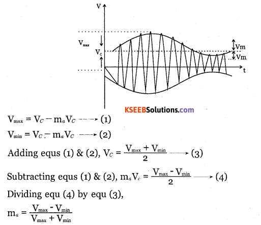
Question 4.
Show that the total power in AM is \(\frac{3}{2}\)
Answer:
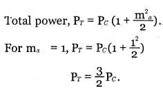
∴ Total power in AM is \(\frac{3}{2}\)
![]()
Question 5.
Describe the basic operation of a varactor diode FM generator
Answer:
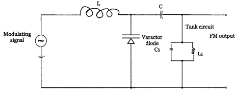
It is based on the principle that the capacitance of varactor diode can be varied with modulating voltage. The varactor diode is placed across the tank circuit. RF choke (L) blocks RF signal but allows modulating signal to pass through. The modulating signal is applied in series with DC bias voltage. The low frequency signal passes through RF choke and applied across varactor diode. The varactor diode changes its capacitance according to modulating signal. Hence total capacitance value in the tank circuit changes and hence oscillator frequency changes. The output is hence a FM wave. Varactor diode modulator is used in automatic frequency control and in remote tuning.
Question 6.
Describe the basic operation of a reactance FM Modulation
Answer:
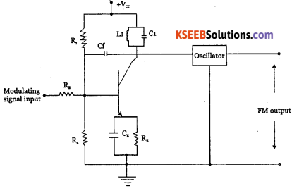
The circuit shows reactance modulator used along with colpitts oscillator. The resistor RB and capacitor Cf are used to provide 90° phase shift between collector voltage and current. This makes circuit work like a voltage-controlled capacitor, which is connected in parallel with tuned circuit of an oscillator.
The changing information signal applied to base has the effect of increasing or decreasing capacitance value. Hence effective capacitance of tuned circuit L, C, changes due to which resonance frequency changes. Thus, oscillator frequency varies according to variations in amplitude of modulating signal and hence the FM wave is obtained.
Question 7.
Explain with circuit diagram the pre-emphasis and de-emphasis processes.
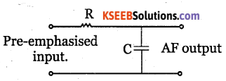
Answer:
Pre-emphasis is the process of boosting the relative amplitudes of high frequency components of modulating signal.
It is done at the transmitter to boost modulating frequencies above 1KHZ. RC high pass filter or differentiator is used as pre-emphasis circuit.
This circuit increases amplitude of modulating signal with increase in frequency.
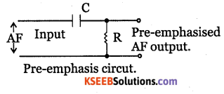
De-emphasis:
It is the process of attenuating relative amplitudes of high frequency components of the modulating signal.
It is done at the receiver. It is a lowpass filter or an integrator. It produces lower output at the higher frequencies because the capacitive reactance of capacitance decreases as frequency increases.
Question 8.
Explain the following characteristics of a radio receiver.
a. Sensitivity
b. Selectivity
c. Fidelity
Answer:
a. Sensitivity of a radio receiver is its ability to respond to weak signal and is expressed as the minimum signal input voltage or power required to produce required output.
b. Selectivity is the ability of the radio receiver to distinguish between required signal to which receiver is turned and the other signal frequencies.
c. Fidelity of a radio receiver is its ability to reproduce the signal that appears in its input faithfully in its output.
Question 9.
What are important considerations while selecting an IF of a radio receiver?
Answer:
- A lower value of IF improves selectivity’ but elimination of image frequency becomes difficult.
- If IF is low, the selectivity becomes two sharp resulting in sideband cutting. Very high selectivity makes a receiver more difficult to tune oscillator circuits.
- IF should not be too high because high IF leads to reduction in selectivity’, gam sue adjacent channel rejection.
![]()
Question 10.
Write a note on choice of local oscillator frequency.
Answer:
If the frequency of local oscillator is higher than the required signal frequency, then maximum to minimum capacitance ratio required by the variable capacitor is 4.4:1 But the tuning capacitors available commercially have a capacitance ratio of 10:1.
If the oscillator frequency is kept lower than the signal frequency, the maximum to minimum capacitance ratio required is 158:1. It is not practicable to make a tunable capacitance with this type of range. Hence the local oscillator frequency is made higher than the signal frequency in all AM receivers.
2nd PUC Electronics Modulation and Demodulation Five Marks Questions and Answers
Question 1.
Explain amplitude modulation. Derive the voltage equation of an AM wave.
Answer:
Let the instantaneous voltage of modulating signal be given by the expression Vm = Vm Sin ωt.
Let the instantaneous voltage of high frequency carrier be given by vc = Vc sinωct. In amplitude modulation, amplitude of carrier varies proportional to instantaneous amplitude of modulating signal.
Hence amplitude of modulated signal is
A = Vc + Vm
= Vc + Vm sin ωmt
\(=\mathrm{V}_{c}\left[1+\frac{\mathrm{V}_{\mathrm{m}}}{\mathrm{V}_{c}} \sin \omega_{\mathrm{m}} \mathrm{t}\right]\)
= Vc[1 + ma Sin ωmt ]
The instantaneous value of amplitude modulated signal is
VAm = A Sin ωct
Vam – Vc[1 + ma Sinωmt] Sin ωct.where ma is called modulation index.
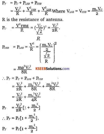
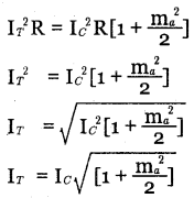
Question 2.
Derive the current and power relations for AM wave in terms of modulation indese.
Answer:
The total power in AM wave is equal to the sum of powers of the carrier, the upper sideband and the lower sideband.
Question 3.
Explain with circuit diagram, the working of collector modulated class C amplifier.
Answer:
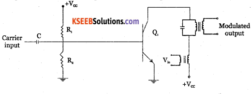
The modulating signal is applied to the collector of the transistor and hence this circuit is called collector modulator It has RF amplifer in class C mode, in which the amplifier conducts only for a portion of positive half cycle of input signal. LC tank circuit is tuned to resonate at carrier frequency. The signal to be modulated is connected to the class C amplifier through the transformer Tr The secondary winding of transformer T connects the modulating signal in series with collector supply Vcc. Thus amplitude of collector current varies with amplitude of modulating signal.
A voltage is induced across the secondary of transformer T when signal is fed to its primary. The induced voltage is added or subtracted from Vcc depending on phase at that instant of time. With change in collector voltage, the transistor output characteristics changes and accordingly Q point changes. Thus amplitude of current pulses through the transistor vary. These current pulses excite tuned circuit to oscillate at required frequency. Hence, we get a sinusoidal RF voltage across tank circuit at carrier frequency whose peak amplitude varies in accordance with the modulating signal. Thus an AM wave is generated.
![]()
Question 4.
Draw the block diagram and explain the various stages of an AM transmitter
Answer:
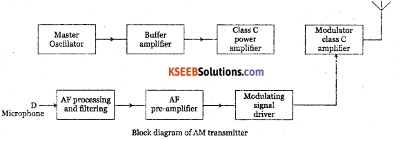
The transmitter performs modulation and raises the power level of a modulated wave to required level for effective radiation.
The microphone converts the audio signal into an equivalent audio electrical signal. The output is filtered to have a bandwidth of 10kHz.
The pre amplifier provides the required voltage amplification. The driver amplifier increases the power level of the signal as required by the high power modulation amplifier.
The high frequency carrier wave is generated by a crystal oscillator which has highest frequency stability. The Carrier signal is fed to a buffer amplifer which is a low gain, high input impedance amplifer which isolates crystal oscillator and the power level of the carrier signal to drive the modulated class C amplifier.
The modulating audio signal and carrier signal are applied to the modulator. The collector modulation is used for modulation in high power transmitter. The transmitting antenna transmits the signal.
Question 5.
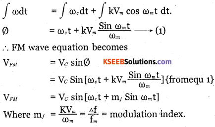
Derive an expression for the instantaneous value of a FM wave.
Answer:
Frequency modulation is the process of varying the frequency of high frequency carrier wave in accordance with instantaneous amplitude of the modulating signal.
Let the modulating signal be given by vm=vm coswt.
Where w is the angular frequency and vm is the peak amplitude. Let the carrier voltage be given by the equation vc= vcsin (Wct +Ø) where wc is the angular frequency of the carrier and Vc is the peak amplitude of the carrier phase angle θ = Wct + θ.
This is instantaneous phase angle of carrier voltage.
Then carrier voltage Vc = Vc sin Ø
The angular frequency \(\omega _{ c }=\frac { d\emptyset }{ dt }\)
or Ø = ∫ ωc dt
The angular frequency of carrier after modulation is
ω = ωc + kvm
ω = ωc + kVmcos ωc t.
Where K is a constant of proportionality called as the modulation deviation constant. On integrating,
Question 6.
With a block diagram, explain the various stages of FM transmitter
Answer:
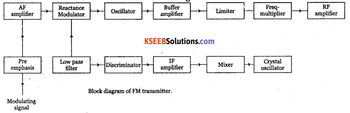
The modulating signal is applied to the pre-emphasis circuit, which improves signal to noise ratio, AF amplifier amplifies output of pre-emphasis. The processed signal is fed to reactance modulator. The reactance modulator uses a transistor or FET connected across tank circuit of carrier oscillator.
The oscillator frequency depends on the tank reactance which in turn depends on the instantaneous amplitude of modulating signal. Thus, output of reactance modulator will be a frequency modulated wave.
The oscillator is followed by a buffer amplifier which isolates oscillator from subsequent stages. The limiter maintains the amplitude constant. Class C power amplifier amplifies modulated wave to required power levels. The FM signal is then fed to the transmitting antenna.
Question 7.
Draw the schematic diagram of a diode detector and describe its operation.
Answer:
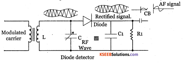
LC tank circuit is used as a parallel resonant circuit. The resonant frequency of the circuit can be varied by varying the value of capacitance C and hence RF signal of any desired frequency can be tuned in.
When a selected modulated signal is applied to the diode, the diode conducts only during the positive half of the modulated wave. Thus the diode removes the entire negative half cycles. Across R1C1 only positive half cycles of carrier modulated wave appears. Thus the low pass filter made up of R1 C1 removes the RF.
During positive half cycle, diode conducts the capacitor C1 gets charged. During negative half cycle of the carrier and diode doesnot conduct but C1 discharges through R1. Hence output is obtained. The spikes can be reduced by proper choice of R1 C1 and depth of modulation. The capacitor CB removes Dc component produced by the detector.
![]()
Question 8.
Explain the basic principle of super heterody AM receiver and explain the function of each block.
Answer:
The super heterodyne AM receiver converts all the incoming radio frequencies into a fixe radio frequency of lower value called intermediate frequency (IF). It uses a local oscillator of frequency higher than the incoming carrier frequency.The first step of the receiver is to select required particular station signal rejecting the rest of signals. The radio waves from the various stations intercepted by the antenna are coupled to the RF amplifier.
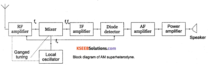
RF section: It is a tuned filter that receives the required stations by tuning the filter to right frequency band. The output of RF stage is fed to mixer stage.
Mixer: It is a kHz device that converts carrier frequency f to a fixed IF of 455 kHz. The oscillator is made to generate a frequency exactly 455 kHz above the incoming carrier frequency f Thus, a constant frequency difference is maintained between local oscillator frequency and incoming RF signal. It is possible due to ganged capacitance tuning where one of the plates of capacitors in RF amplifier, mixer and local oscillator are connected to single shaft. Required selectivity is possible by producing IF signal.
Local oscillator: It is a Colpitts oscillator which generates a sine wave.
IF amplifier: It has two or more stages of 455 kHz frequency tuned voltage amplifiers for giving better selectivity and stability. All signals that are converted down that are T-f and falling within the pass band of If amplifier will be amplified and passed on to next stage.
Detector: It seperates modulating signal from the AM signal. It is a diode detector which gives excellent fidelity. It first eliminates negative half cycles of IF wave and then filters the high frequency waves. The modulating signal is then fed to AF amplifier.
AF Amplifier: Audio signal is first amplified using RC coupled voltage amplifier to raise its level to drive a power amplifier.
Power amplifier: It is a push pull power amplifier designed to have a minimum bandwidth of 5kHz. The audio power amplifier output is fed to loud speaker through impedance transformer. The loud speaker reproduces the original information.
Question 9.
Draw the block diagram of an FM receiver and explain its working.
Answer:
RF amplifier: The RF amplifier increases the signal strength before the signal is fed to mixer
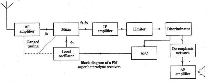
when turned to the desired frequency. The RF amplifier is designed to handle large bandwidth of 150 kHz.
Mixer: the incoming RF signal of frequency fm is applied to a mixer which also receives the output from the local oscillator. A new frequency called intermediate frequency IF is produced whose value is difference of local oscillator signal f and signal frequency f.
Local oscillator: the receiver converts incoming carrier frequency to the IF by using local oscillator frequency higher than incoming tuned frequency. Colpitts oscillator is used as the local oscillator.
IF amplifier: IF signal is amplified by one or more number of amplifiers, which raises the strength of IF signal. It has multistage class A amplifier providing better selectivity and gain.
Limiter: It removes all the amplitude variation in FM signal caused by noise. Differential amplifiers are preferred for limiter.
Discriminator: It recovers the modulating signal from the IF signal. It converts frequency variation into corresponding voltage variation and produces the modulating signal. De-emphasis network: It reduces the relative amplitude of high frequency signals that are boosted in the transmitter and brings them back to their original level.
AF amplifier: It amplifier the modulating signal recovered by the FM detector. The speaker converts the electrical signal into sound signal.
Question 10.
Draw the equivalent circuit of transmission line. Explain the primary and secondary constants.
Answer:
For low frequency
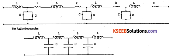
Primary constants:
- The series resistance per unit length R is proportional to the square root of frequency.
- The inductance L per unit length for a 2 wire T-line is \(\mathrm{L}=\frac{\mu}{2} \log \left(\frac{2 \mathrm{D}}{\mathrm{d}}\right)\) where pt is the permeability.D is distance between two wires. And d is diameter of each wire.
- The capacitance C per unit length,
\(C=\frac{\mu}{\log \frac{2 D}{d}}\) - Where e is the permittivity of free space, D is distance between 2 wires and d is the distance between the plates of capacitor.
Secondary constants of T-line:
- The series impedance of T-line is Z=R+jwL.
- The shunt admittance of T-line is y=G+JWC are the two secondary constants.
Question 11.
What is an antenna? Briefly explain any four types of antennas.
Answer:
An antenna is a device that radiates and receives electromagnetic waves.
Helical antenna: It has a conducting wire wound in the form of a helix. They are mounted over ground plane and are used at earth base stations in satellite communication systems.
Yagi antenna: It is an array of parallel, straight antenna elements, one or more driven and one or more parasitic. Yagi, the Japanese antenna expert researched how parasitic elements effects the directional properties of an antenna.
Loop antenna: It receives radio signals more efficiently. The loop is wound on a form, which may be box or spiral wound. The core may be air or powdered iron compound. Its gain is less but it has less noise pick up.
Horn antenna: It has a flaring metal wave guide shaped like a hom to direct radio waves in a beam. These are used at UHF and microwave frequencies above 300 MHx. The maximum radiation is along the axis of the hom.
Question 12.
Distinguish between analog comjnunication and digital communication
Answer:
| Analog communication | Digital communication |
| 1. Analog signal is a signal having infinite number of values. | 1. Digital signal is represented by finite set of discrete values. |
| 2. It uses AM.FM,PAM, PWM types of modulation. | 2. It uses PCM. |
| 3. Needs simple circuitry’. | 3. Needs complex circuitry. |
| 4. It has low transmission speed and noise level. | 4. It has high transmission speed and low noise level. |
| 5. Their bandwidth is less. | 5. Thier bandwidth is large. |
| 6. Signal transmitted is analog. | 6. Digital signals are coded using 1 and 0. |
Question 13.
Draw the block diagram of digital communication and explain the function of each block.
Answer:
Source encoder: Converts analog signal into binary code
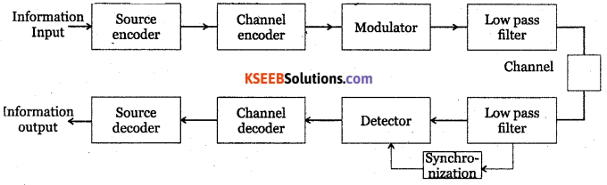
- Channel encoder: Generates channel code word from the source code words.
- Modulator: Modulates the channel code words into a continuous wave.
- Low pass filter: Allows only lower frequencies and blocks the other frequencies.
- Synchronisation: Is required to demodulate a carrier modulated wave.
- Demodulator: Converts continuous waveform into ordinary signal.
- Channel decoder: Decodes the channel code word.
- Source decoder: Converts channel decoder code word into information signal.
Problems with Solutions
Question 1.
Calculate the modulation index if sinusoidal wave of peak value 4V is used to modulate the carrier of peak value of 5V.
Answer:
Modulation index = \(\mathrm{m}_{a}=\frac{\mathrm{V}_{m}}{\mathrm{V}_{c}}=\frac{4}{5}=0.8\)
![]()
Question 2.
The maximum and minimum amplitudes of a sinusoidal modulated wave are 4V and IV. Determine the percentage modulation.
Answer:
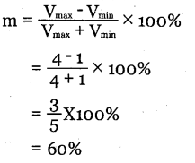
Question 3.
The amplitude of signal and carrier of an AM wave are 4V and 6V respectively. Calculate the Vmin of AM wave.
Answer:
Vmin Vc – ma Vm
= Vc – Vm for m = 1
= 6 – 4
= 2V
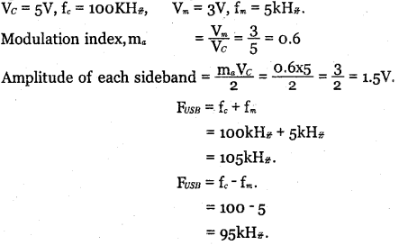
Question 4.
A sinusoidal carrier signal of peak amplitude 5V and frequency 100 kH is amplitde
modulated by a 5 kIir signal of peak amplitude 3V. What is modulation index? Draw the
spectrum of modulated signal.
Answer:
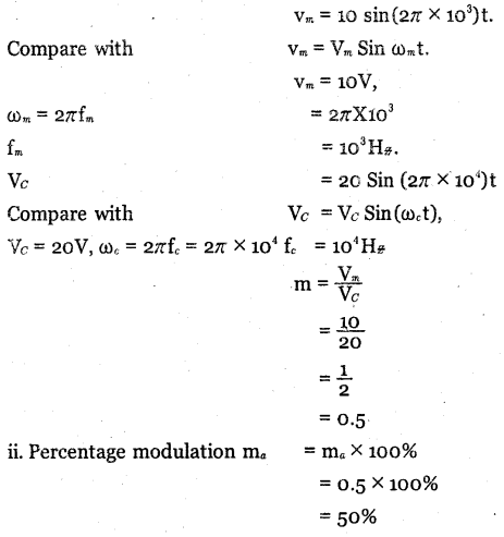
Question 5.
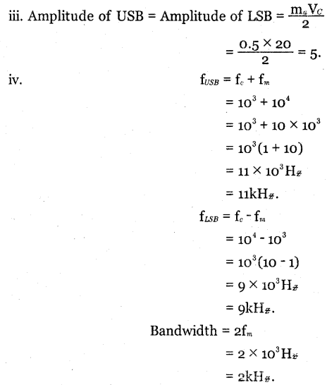
A modulating signal lOsin (2π x 103t) is used to modulate carrier signal 20sin(27π x104)t. Find.
- Modulation index
- Percentage modulation
- Frequencies of sideband components and their amplitudes.
- Band width of modulated signal.
Answer:
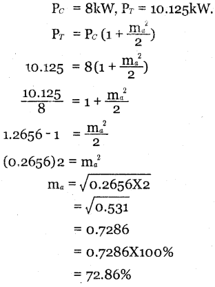
Question 6.
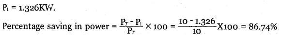
A transmitter radiates 8 kW of power with carrier unmodulated and 10.125 kW when modulated. Calculate the depth of modulation.
Answer:
![]()
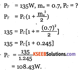
Question 7.
A radio transmitter radiates a total power of 135W when modulation index is 0.7. What is the carrier power radiated by the transmitter?
Answer:
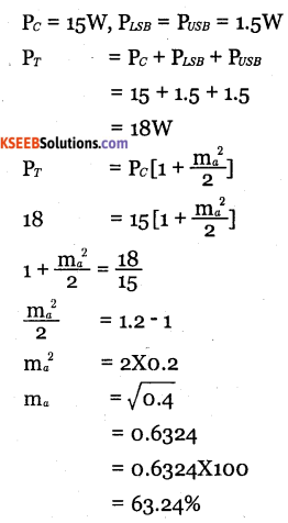
Question 8.
An AM signal has 15W carrier and 1.5W in each sidehand. What is percentage of modulation?
Answer:
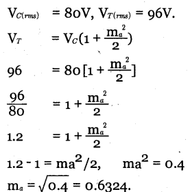
Question 9.
The rms value of a carrier voltage is 80V. After amplitude modulation by a sinusoidal audio signal, rms value of the carrier voltage becomes 96V. Determine modulation factor.
Answer:
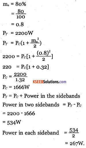
Question 10.
Determine the power content of the carrier an each of side bands of an AM wave having a percent modulation of 80% and a total power of 2200W.
Answer:
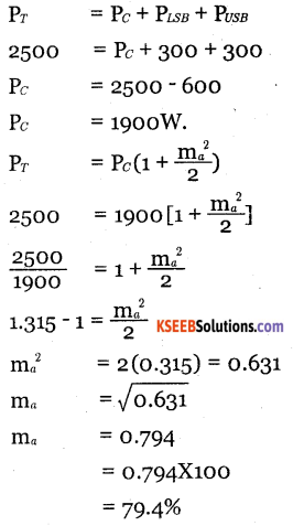
Question 11.
Determine the percent modulation of an AM wave whose total power content is 2500W and whose sidebands each contain 300W.
Answer:
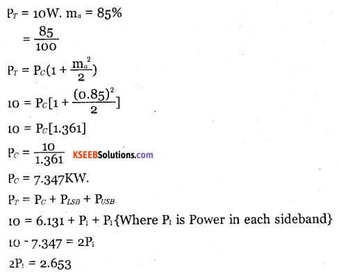
Question 12.
An AM transmitter radiates 10kW power at 85% modulation. What would be power saving if the carrier and one of sidebands are suppressed?
Answer:
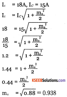
Question 13.
The antenna current of an AM transmitter is 15A when unmodulated and rises to 18A
when modulated. Calculate the depth of modulation.
Answer:
Question 14.
An antenna has an impedance of 50Ω. An unmodulated AM signal produces a current of 4.8A. The percentage of modulation is 90. Calculate
- The carrier power
- The total power
- Sideband power
Answer:
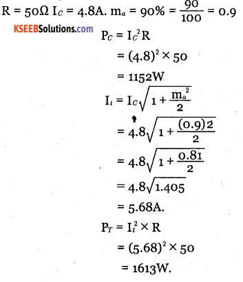
Power in sidebands = Pt – Pc
= 1613 -1152
= 461W
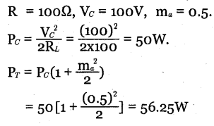
Question 15.
What is the power developed in an AM wave in a load of 100Ω, when peak voltage of carrier is 100V and modulation index is 0.5?
Answer:
Question 16.
An FM signal has a deviation of 10kHz and modulating frequency of 5 kHz. Calculate the modulation index.
Answer:
![]()
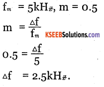
Question 17.
Calculate the frequency deviation for an FM signal with a modulating frequency of 5 kHz and modulation index of 0.5. in = 5kHz, m = 0.5
Answer:
Question 18.
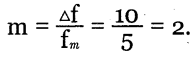
Determine modulation index of an FM carrier having a frequency deviation of 25 kHz and modulating signal of 5kHz. Also determine carrier swing.
Answer:
Δf = 25 kHz, fm = 5kH
\(m=\frac{\Delta f}{f_{m}}=\frac{25}{5}=5\)
Carrier swing, Cs = 2.Δf
= 2 x 25kHz
= 50 kHz
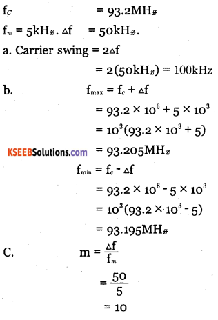
Question 19.
A 93.2 MHz carrier is frequency modulated by a 5 kHz sinewave. The resultant FM signal has a frequency deviation of 50kHz.
a. Find the carrier swing of the FM wave.
b. Determine highest and lowest frequencies attained by modulated signal.
c. What is modulation index of FM wave
Answer:
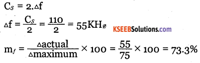
Question 20.
Determine the percent modulation of an FM signal which is being broadcast in the 88108 MH* band, having a carrier swing of 110 kHz.
Answer:
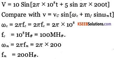
Question 21.
An FM wave is represented by 10 sin (2π x 10s π+ 5 sin 2n x 200t) Determine
- Carrier and modulating frequency.
- Modulation index and maximum deviation.
Answer:
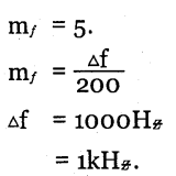
Question 22.
A frequency modulated signal is given by 75 sin[2π x 90 x 106t + 6 sin 200π. Determine a. Modulating signal frequency.
b. Carrier frequency.
c. Peak deviation.
d. The deviation ratio
e. The modulation index.
Answer:
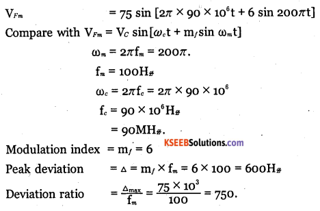
Question 23.
Determine the frequency of modulating signal which is producing an FM signal having a bandwidth of 60kHz when the frequency deviation of FM signal is 10kHz,
Answer:
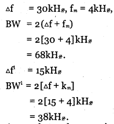
Question 24.
An FM radio has a frequency deviation of 30kHz. The modulating frequency is 4 kHz. Calculate the bandwidth needed. What will be the new bandwidth if the deviation is reduced to 15 kHz.
Answer:
![]()
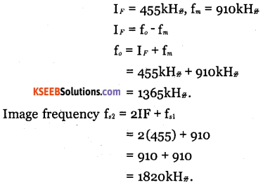
Question 25.
A superheterodyne receiver using an intermediate frequency of 455 kHz is receiving a modulated signal of 910 kHz. What is the frequency of local oscillation? What would be its image frequency?
Answer: